Dexter Nev-R-Adjust 10-72: Complete Brake Wiring & Assembly Guide
Proper wiring and assembly of the Dexter Nev-R-Adjust 10-72 electric brake system can mean the difference between reliable stopping power and roadside frustration. This guide breaks down the exact wiring sequence, magnet orientation, and voltage checks needed to get it right the first time.
What Makes the Dexter Nev-R-Adjust 10-72 Wiring Different From Standard Brakes?
The Nev-R-Adjust 10-72 uses a self-adjusting mechanism that relies on precise magnet-to-armature spacing, which directly impacts wiring integrity. Unlike traditional drum brakes where you manually adjust star wheels, this system expects zero maintenance once assembled. That means any wiring error—like reversed polarity on the brake magnet—won’t trigger an adjustment cycle, leading to uneven pad wear and reduced braking force.
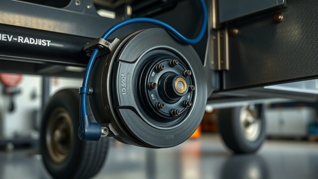
The 10-72 designation refers to the brake assembly’s 10-inch drum diameter and 2-inch-wide shoe set, common on tandem-axle trailers up to 7,000 lbs capacity. The wiring harness uses a standard 12-gauge wire for the magnet circuit, terminating in a 6-pole connector for the trailer control unit. The self-adjusting lever sits inside the backing plate, and its sensor cable must be routed through the dust shield opening without kinking.
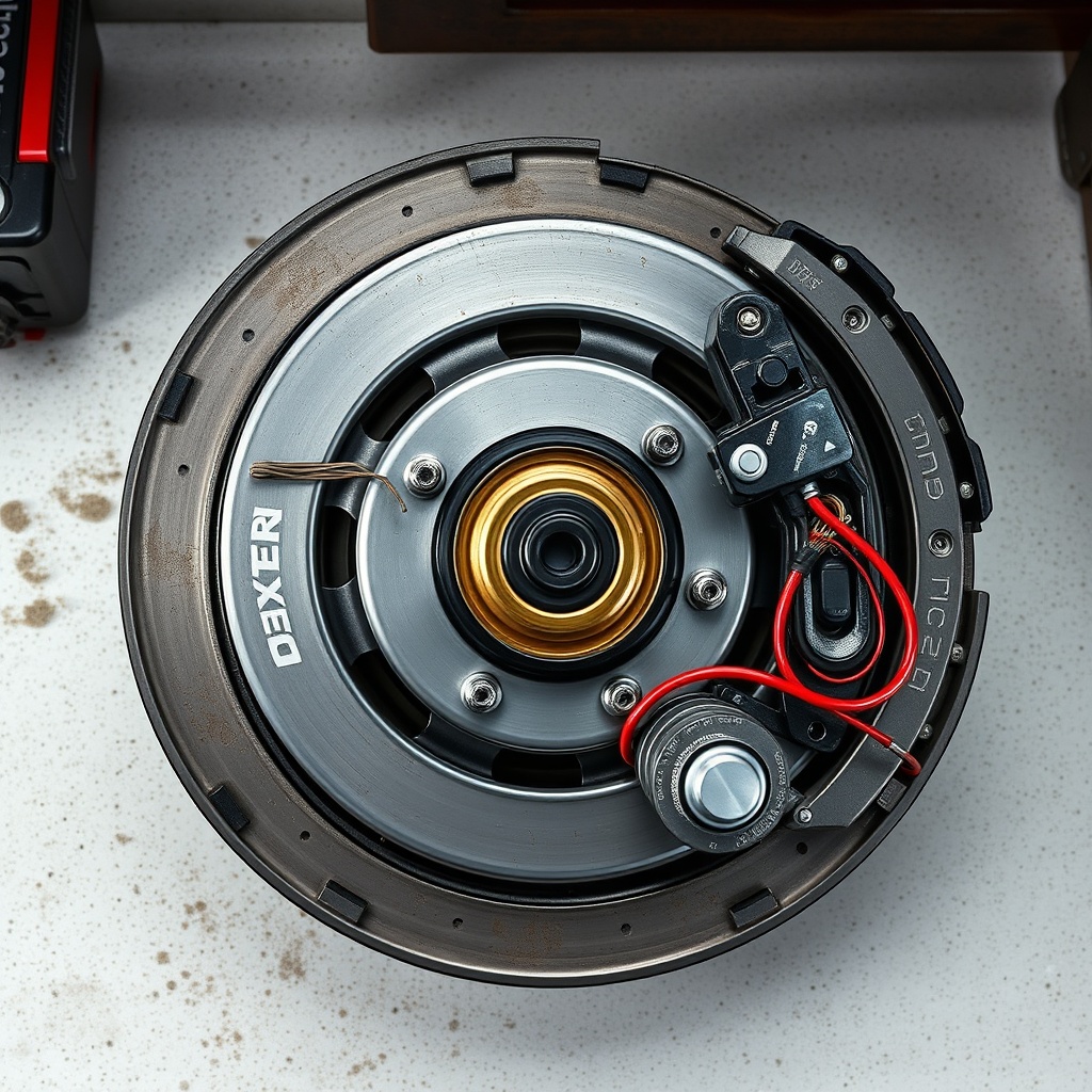
Pay close attention to the magnet lead orientation: the red wire connects to the positive terminal of the brake controller output, while the black wire connects to ground. Cross these, and the magnet will energize in reverse, causing the armature to pull away from the drum rather than engage it. On the 10-72, the ground circuit also serves as the return path for the self-adjusting solenoid, so a bad ground trips both functions.
Which Wire Color Goes Where on the Dexter Nev-R-Adjust 10-72 Magnet?
The factory standard for the Dexter Nev-R-Adjust 10-72 magnet wiring is straightforward: red to the brake controller output (positive), black to the trailer frame ground (negative). The magnet itself has two 5/16-inch ring terminals crimped onto 12-gauge wire. You should verify continuity from each terminal to the magnet coil before installation—a common issue is a loose crimp that passes a visual check but fails under vibration.
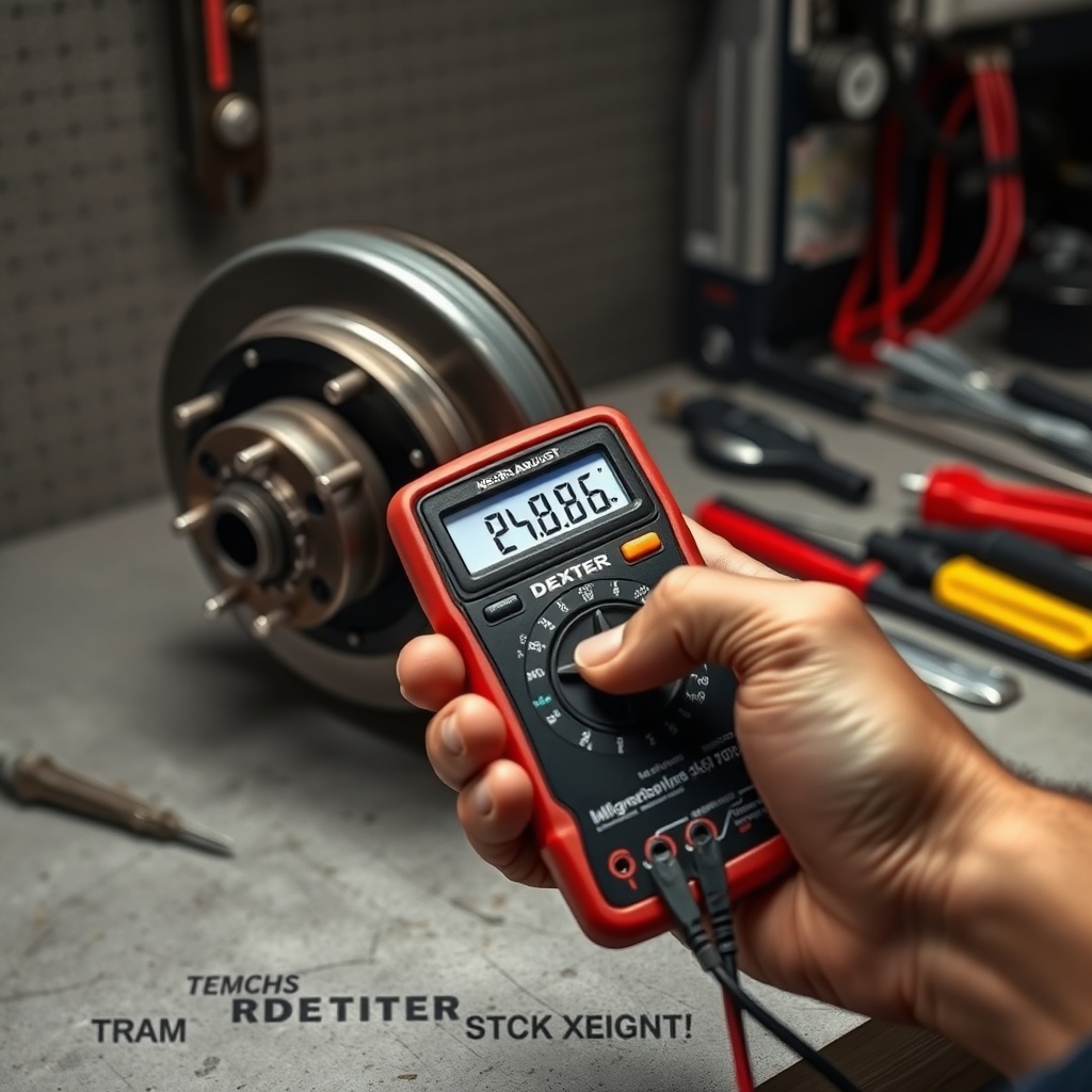
Use a digital multimeter set to resistance (Ohms) to check the magnet: a healthy 10-72 magnet reads between 3.2 and 3.8 ohms at 68°F. If you get an open circuit (infinite resistance) or a short (less than 2 ohms), replace the magnet immediately. Do not rely on the wire color alone—poorly stored assemblies may have wire swaps from previous maintenance. The 10-72 also includes a temperature sensor wire (usually white) that connects to the brake controller to prevent overheating. This wire routes to terminal 4 on the trailer plug.
When splicing into the trailer harness, use heat-shrink butt connectors rated for outdoor use. The 10-72’s magnet draws about 3.5 amps at 12V fully engaged, so 14-gauge wire is acceptable for short runs, but 12-gauge is preferred for lengths over 20 feet. Secure all splices with zipties at 12-inch intervals to prevent chafing against the frame.
How to Assemble the Self-Adjusting Mechanism Without Binding
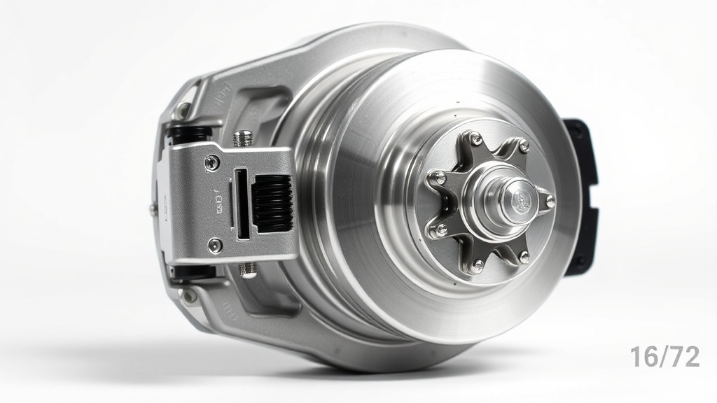
The self-adjusting assembly on the 10-72 consists of a star wheel, a sensing lever, and a return spring. The lever must sit perpendicular to the brake shoe web when the shoes are fully retracted. If the lever tilts more than 5 degrees out of square, it will drag on the drum and cause premature wear.
Start by lubricating the star wheel threads with white lithium grease—do not let grease contact the brake lining surface. Thread the star wheel onto the adjusting bolt until the shoes just touch the drum, then back it off exactly 6 clicks. This sets the baseline clearance for the self-adjuster to take over. On the 10-72, one click corresponds to roughly 0.060 inches of shoe expansion, so six clicks gives you 0.360 inches of adjustment range—enough for normal lining wear over a season.
Route the sensor cable through the backing plate’s dedicated grommet. Cable routing matters: if the cable crosses the magnet arm, it can vibrate against the armature during braking. Use a cable tie to secure it to the backing plate at least 2 inches away from the magnet axis. After assembly, spin the drum by hand—you should hear a light scraping, not a grinding sound. Use a feeler gauge: 0.030 inches clearance between shoe and drum is ideal for unloaded operation.
| Condition | Severity Level |
|---|---|
| Magnet resistance outside 3.2–3.8 ohms | Needs attention soon |
| Sensor cable touching magnet arm | Usually not urgent (fix at next maintenance) |
| Star wheel locked after 2-3 brake applications | Needs attention soon |
| Brake drum temperature above 250°F after 30 min highway | Needs attention soon |
| Self-adjuster lever tilted more than 5 degrees | Needs attention soon |
| Slight scraping sound during rotation | Usually not urgent |
What Voltage and Current Values Should You See at the Brake Controller?
A properly wired Dexter Nev-R-Adjust 10-72 system should show 12.0–12.6 volts at the brake controller output terminal (usually blue wire) with the battery fully charged. When you manually apply the brake slider, voltage should ramp smoothly from 0 to 12 volts over about 1.5 seconds—the self-adjuster needs a slow voltage rise to engage the locking pawl correctly.
Measure current with a clamp meter around the blue wire: at full brake application with a loaded trailer (7,000 lbs), you should see 3.2–3.8 amps per brake assembly. For a pair of 10-72 brakes on one axle, that totals 6.4–7.6 amps. If current exceeds 9 amps, one of the magnets is likely shorted internally. If current reads below 2.5 amps, you have a high-resistance connection—check ring terminal crimps and ground connection at the trailer frame.
The self-adjuster circuit includes a 0.5-amp fuse in the brake controller line. If this fuse blows, the adjuster stops working, and you’ll lose automatic clearance maintenance. Always carry spare 0.5-amp fuses—they are not the same as 1-amp or 2-amp fuses commonly found in auto parts stores.
How to Test the Self-Adjuster Circuit After Assembly
After wiring the 10-72 brakes, perform a bench test before mounting the drums. Connect a 12V battery directly to the magnet circuit (red positive, black negative) and listen for the adjusting lever clicking. You should hear 3-5 distinct clicks as the star wheel rotates counterclockwise. If the lever spins freely without clicks, the pawl spring is displaced. If the lever doesn’t move at all, the solenoid inside the adjuster is dead—replace the adjuster assembly.
Next, install the drum and rotate it backward by hand. The self-adjuster should engage when the drum rotates in the forward direction of travel. For a trailer on a vehicle, forward means the drum spins away from you when viewed from the spindle side. Backward rotation should not activate the adjuster. If it does, the sensor lever is installed upside-down—remove the backing plate and flip the lever 180 degrees.
Finally, load test with a trailer: drive at 20 mph in an empty parking lot, apply brakes firmly, then immediately check drum temperature with an infrared thermometer. All four drums should read within 20°F of each other. A cold drum indicates a stuck adjuster or open magnet circuit on that wheel.
What Owners Say About the Dexter Nev-R-Adjust 10-72 Wiring
Owners on the TrailerHub forum who have wired the 10-72 system consistently note two things: the self-adjuster works reliably once the magnet polarity is correct, but you must test the sensor cable routing. “My first install, I ziptied the sensor cable too tight and it rubbed through in 300 miles. Replaced it with extra slack and no issues since,” one owner shared.
Another frequent observation: the ground wire on the 10-72 is longer than necessary, leading some to trim it—a mistake because any modification voids the water-resistant grommet seal. “I cut the ground by two inches to keep it tidy, and two months later the adjuster stopped working. Turns out the shorter wire pulled the connector out of alignment. I installed a replacement harness and left it full length.”
A third owner pointed out that using dielectric grease on the magnet ring terminals made a noticeable difference in corrosion resistance after a winter of salt-exposure towing. “I’ve had standard brakes rust at the connector in one season. With the Nev-R-Adjust and dielectric grease, three seasons later the terminals still look new.”
Frequently Asked Questions About Dexter Nev-R-Adjust 10-72 Brake Wiring
Q1: Can I use a standard 7-pin trailer connector with the 10-72 brakes?
Yes, a standard 7-pin round connector works. The blue wire connects to pin 2 (brake controller output), white goes to pin 1 (ground), and the self-adjuster temperature sensor wire connects to pin 4 (auxiliary 12V). Ensure your trailer’s 7-pin connector is wired to the Vehicle Trailer Association (VTA) standard.
Q2: Does the self-adjuster require special brake controllers?
No, any proportional or time-delayed brake controller works. However, the 10-72 adjuster performs best with a proportional controller because the slow voltage rise matches the adjuster’s engagement curve. Time-delayed controllers that jump to full voltage instantly can cause the adjuster pawl to skip teeth.
Q3: How often should I check the wiring on the 10-72?
Inspect the wiring and magnet resistance at the start of each towing season, and at every 3,000 miles. Check the self-adjuster function (an audible clicking test) every 1,000 miles. Saltwater exposure requires inspection every 6 months regardless of mileage.
Q4: Is it possible to wire the 10-72 brakes in series rather than parallel?
No, never wire the magnets in series. Each 10-72 brake magnet requires 12V input directly. Wiring them in series drops voltage across each magnet to 6V, reducing braking force by about 70% and causing the self-adjuster to lock up prematurely. Always wire each brake independently to the brake controller’s output wire.
Q5: What causes the self-adjuster to stop working after a rainy trip?
The most common cause is water ingress into the sensor cable grommet. Check the grommet is fully seated and not cracked. If the adjuster itself is wet, dry it with compressed air and apply a light coating of silicone spray to the moving parts—do not use WD-40, which attracts dust. If the problem persists, replace the grommet and re-seal with silicone-based dielectric compound.
Q6: Can I replace the magnet on the 10-72 without removing the brake assembly?
Yes, but it’s tight. You need to remove the drum, then unbolt the two 5/16-inch bolts holding the magnet bracket. The magnet wire terminals are accessed through the backing plate opening. If you have difficulty, removing the backing plate entirely gives better access, but adds about 20 minutes per wheel. Replace the magnet as a complete assembly—never reuse old magnet wires.